
AI chip manufacturers have introduced a silent crisis into the heart of the data center: heat. A single modern GPU or CPU package used for AI training can draw over 1,100 Watts of power, concentrating a massive thermal load into a space that traditional air-cooling systems were never designed to handle. For the 200 MW AI Factory, the cooling solution is no longer a secondary infrastructure concern; it dictates the entire facility’s architecture, cost, and ultimately, its viability.
A complete cooling solution for an AI Factory is a complex, multi-layered system that moves heat from the silicon to the rack, and finally out of the building.
Traditional Air Cooling: The Foundation
While liquid cooling is the future, nearly all AI factories still rely on core air-handling infrastructure for facility cooling, especially for networking and storage equipment.
- Hot/Cold Aisle Containment: This is the fundamental strategy. Cold air is delivered to the cold aisle (the front of the racks) and is drawn into the server equipment. The heated air is exhausted into the hot aisle (the back of the racks) and returned to the cooling units, preventing the mixing of hot and cold air and maximizing cooling efficiency.
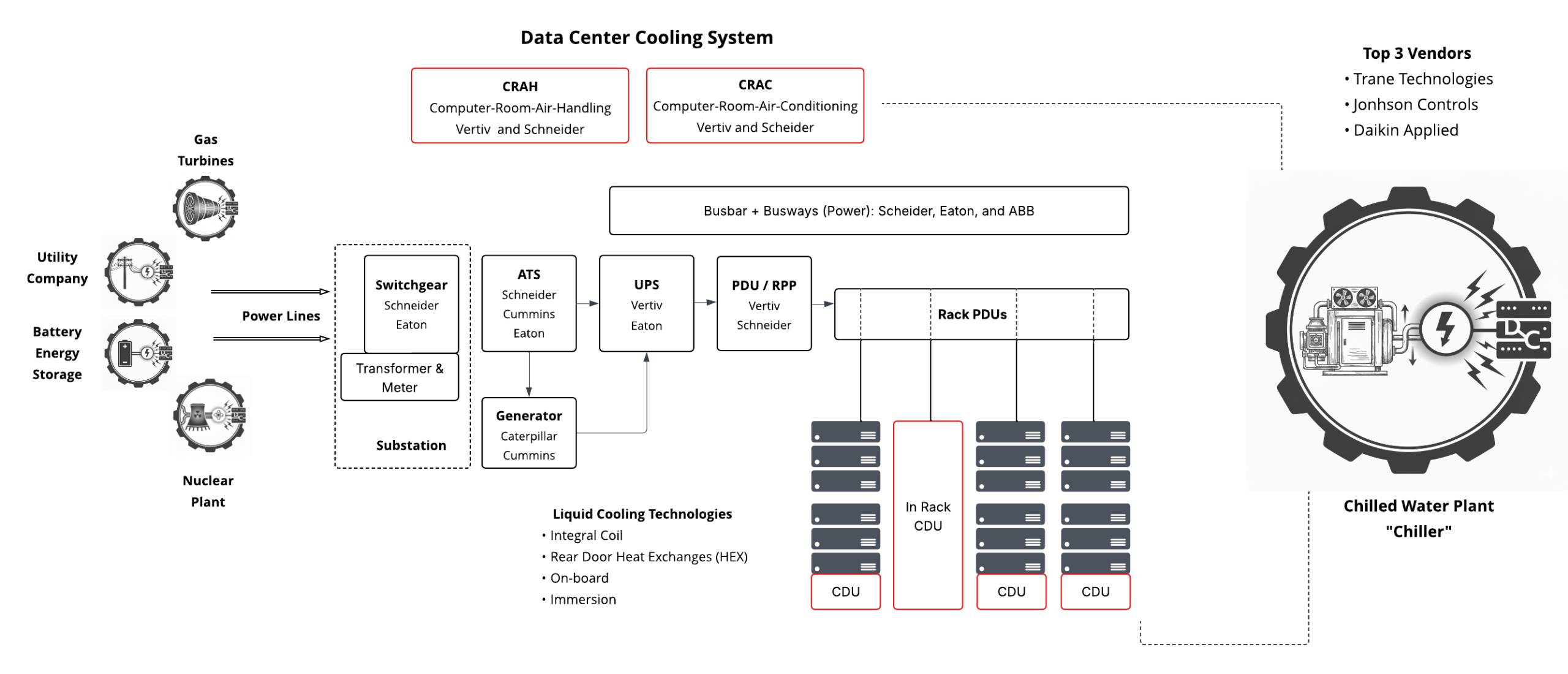
- CRAC vs. CRAH Units: These large units manage the climate within the data hall:
- CRAC (Computer Room Air Conditioner): A self-contained unit that uses a direct expansion (DX) mechanical refrigeration cycle (like a home A/C) to cool the air. Typically less efficient and used in smaller or legacy data halls.
- CRAH (Computer Room Air Handler): The preferred system for modern, hyperscale facilities. It uses fans and a cooling coil through which chilled water is circulated. It does not contain the refrigeration unit; it is simply an air-to-water heat exchanger, making it far more efficient and scalable.
The Chilled Water Plant: The Facility Backbone
The chilled water plant provides the necessary “cold” medium for the CRAH units and the liquid cooling systems. It is the heart of the facility-level cooling loop.
- Chiller: Uses a refrigeration cycle to cool water to a specified temperature (e.g., 45°F / 7.2°C).
- Pumps: Circulate the chilled water (the Facility Water Supply, or FWS) through the entire data center campus and back to the chillers.
- Cooling Tower: Rejects the heat absorbed by the chillers into the atmosphere, often via evaporation.
Direct Liquid Cooling (DLC): The AI Necessity
When rack densities soar past 30 kW and up to 150 kW per rack, air is no longer a viable medium. Direct Liquid Cooling (DLC) systems use a dielectric fluid to capture heat right at the chip.
- Cold Plates (Direct-to-Chip): The most common form of DLC. A metal block, or cold plate, is mounted directly atop the high-heat-generating components (CPUs, GPUs). The coolant flows through micro-channels within the plate, absorbing the heat right at the source, capturing up to 98% of the heat generated by the component.
- Coolant Distribution Unit (CDU): The critical piece of the plumbing. The CDU acts as the heat exchanger and pump system between the facility water (FWS) loop and the closed, clean, dielectric coolant loop running to the chips.
- In-Rack CDU: A 4U to 8U unit installed directly into the rack, typically cooling one or two adjacent racks.
- In-Row / Floor-Mount CDU (CDU at Bottom of Rack): A larger, dedicated unit that sits outside the rack or in the row and can support multiple racks, critical for scaling out high-density clusters. For example, Supermicro utilizes 1.8 MW in-row CDUs to support its large GPU clusters.
Example: Supermicro’s Liquid-Cooled GPU Cluster
Hyperscale players are deploying rack-scale solutions like Supermicro’s liquid-cooled NVIDIA HGX B300 systems. These systems are designed to house up to 144 GPUs in a single rack, achieving massive power density. The entire system relies on DLC, with cold plates on all high-TDP components, all fed by an external CDU system that manages the primary and secondary plumbing loops:
- Primary Loop (Facility Side): Chilled water (FWS) from the central chilled water plant runs to the CDU.
- Secondary Loop (IT Side): The CDU contains a heat exchanger that cools the clean, dielectric fluid, which is then pumped to the racks and circulated through the cold plates on the CPUs/GPUs. This secondary loop maintains fluid temperatures above the dew point to prevent condensation.
200 MW AI Factory: Cooling Component Bill of Materials (BoM)
The cooling load for a 200 MW facility is immense. Assuming a 100 MW IT load and a 50 MW cooling load (resulting in a Power Usage Effectiveness, or PUE, of 1.5):
| Component | Function & Specs for 200 MW Site | Estimated Quantity (IT Load 100 MW) | Top Manufacturers |
| Chillers (Large) | Provides 45°F chilled water. Capacity ~2,000 to 4,000 tons per unit. | 25-35 units (in N+1/2N redundancy) | Johnson Controls (YORK), Carrier, Trane, Daikin |
| Cooling Towers | Rejects heat to the atmosphere. Often evaporative. | 40-60 cells (paired with chillers) | Baltimore Aircoil (BAC), Evapco, Marley (SPX) |
| Pumps | Circulate chilled water (FWS) throughout the campus. | Hundreds (Primary, Secondary, Condenser loops) | Grundfos, Flowserve, Bell & Gossett |
| CRAH/CRAC Units | Provide ambient air cooling for non-DLC equipment and humidity control. | 100-200+ units (depending on facility design) | Vertiv, Schneider Electric (APC), STULZ, Rittal |
| Coolant Distribution Unit (CDU) | Facilitates the liquid-to-liquid heat exchange and pumps the IT coolant loop. | ~55-65 units (1.8 MW to 2.0 MW capacity each) | Vertiv, Schneider Electric (Motivair), CoolIT Systems, Asetek |
The Next Wave: Cooling Innovations
Existing hybrid air/DLC systems are rapidly becoming insufficient as chip power density continues to climb. New technologies are being aggressively deployed to meet the heat demands of the AI Factory:
- Two-Phase Immersion Cooling: Servers are submerged in a tank of engineered dielectric fluid that boils directly off the hot components, turning to vapor. The vapor rises to a condenser coil at the top of the tank, turning back into liquid, completing a highly efficient, closed-loop cycle.
- Microfluidic Cooling: This innovative technology etches tiny micro-channels, similar to a human hair, directly into the back of the silicon chip itself. Coolant flows through these channels, pulling heat away at the source rather than through a traditional cold plate and multiple insulating layers. Companies like Microsoft have announced breakthroughs in this area, aiming to push thermal performance limits far beyond current cold plate systems.
- Direct Heat Re-use: New designs, especially with liquid cooling, allow the 100°F coolant to be used for secondary purposes, such as heating nearby buildings or greenhouses, drastically improving the overall sustainability and efficiency of the facility.
The race for AI dominance has thus become a race for cooling capacity, driving unprecedented innovation in fluid dynamics, heat transfer, and thermal engineering.